WBS @ Westmount
Post Added 07/11/2012
Do you have a Cordless Drill or any other cordless
device that uses NICad battery's that will not hold
charge?
Well this post may just save you some money and restore your Cordless
drill back to a usable condition
What Prompted me to create this post
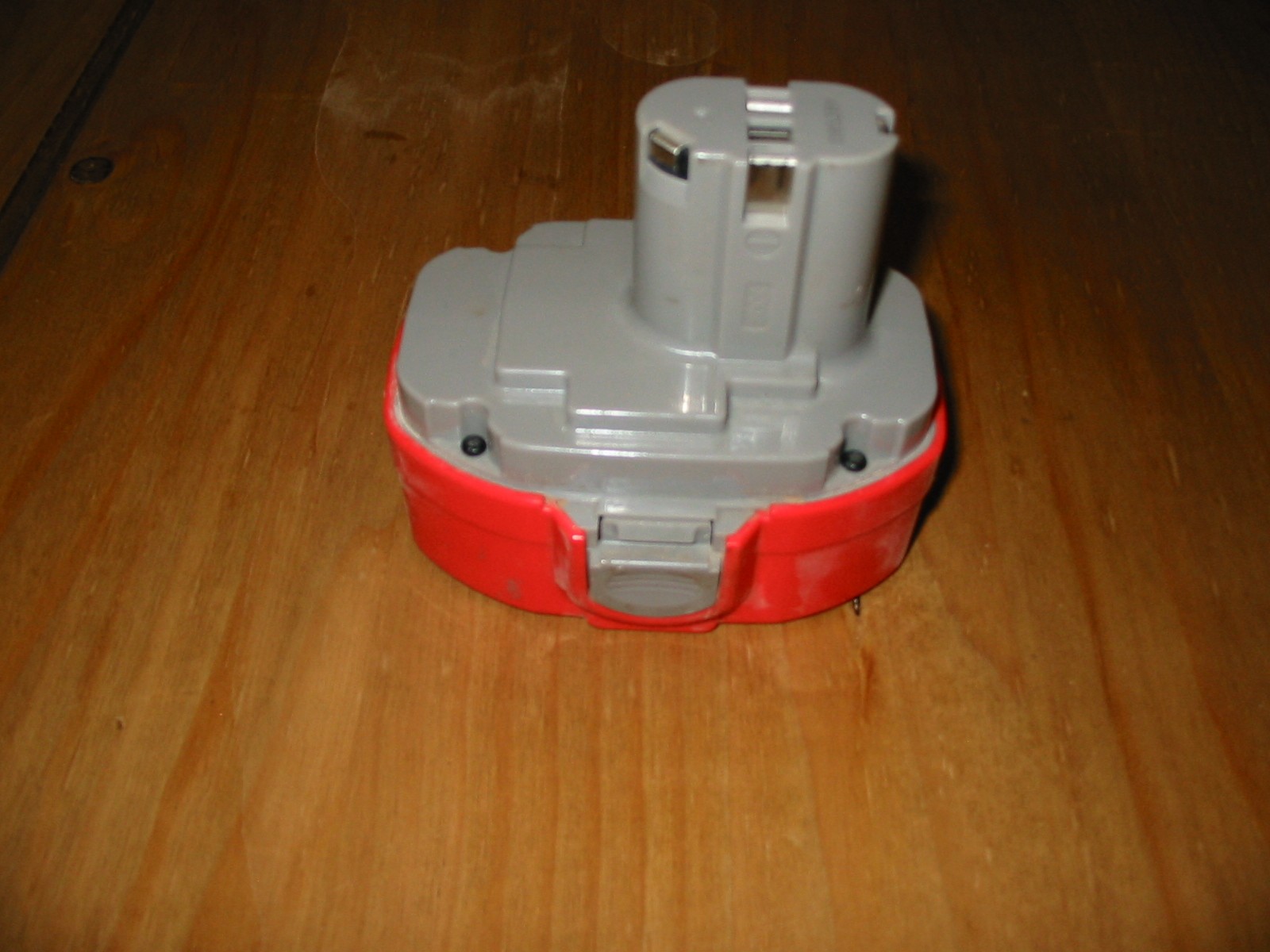
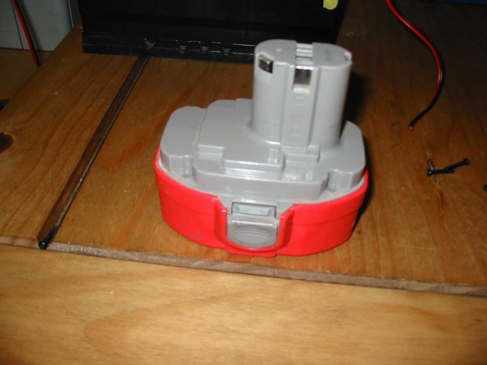
About 2 years ago i purchased a Makita 8391DWPE 18v.
The tool worked without fault until this year when i noticed the battery's
where noticeably not holding the charge
The drill came with 2 Battery's and a 30 Min Charger and it has always
worked well.
Last Weekend i did some work and due to the one battery only lasting for
about 2 mins from full charge and about 5 mins on the second battery
enough was enough i decided to look for a new drill.
But i was unable to find one that met the specification within a cost i
wanted to pay.
2 Replacement battery's from screwfix would cost me nearly as much as
a new drill with 2 battery's so there was no way i would follow that path
just out of principle.
So what did I do?
Being a practical person i did some research on the Net about Route
cause and fix processes to allow me to understand base information to
allow me to adopt my own DIY Nicad Battery Repair ( Regeneration )
Did My DIY Nicad Fix Work
YES It Did
I will add Pictures and instructions how i turned my dead Makita
8391DWPE 18v into a fully functional unit for free
Full Detail and pictures to be added Weekend 11/11/2012.
Process Walkthrough

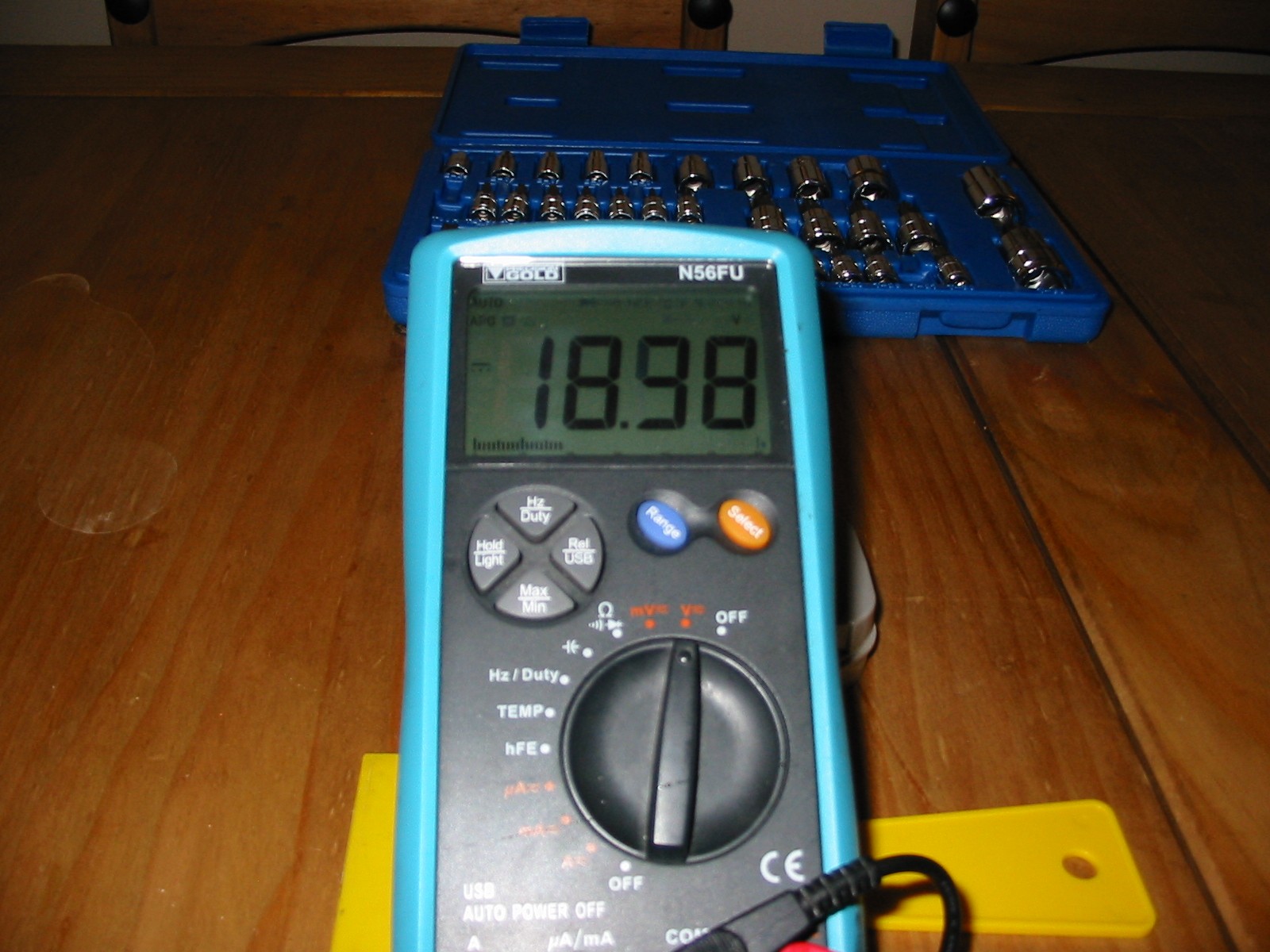
1. check voltage of the battery for reference voltage.
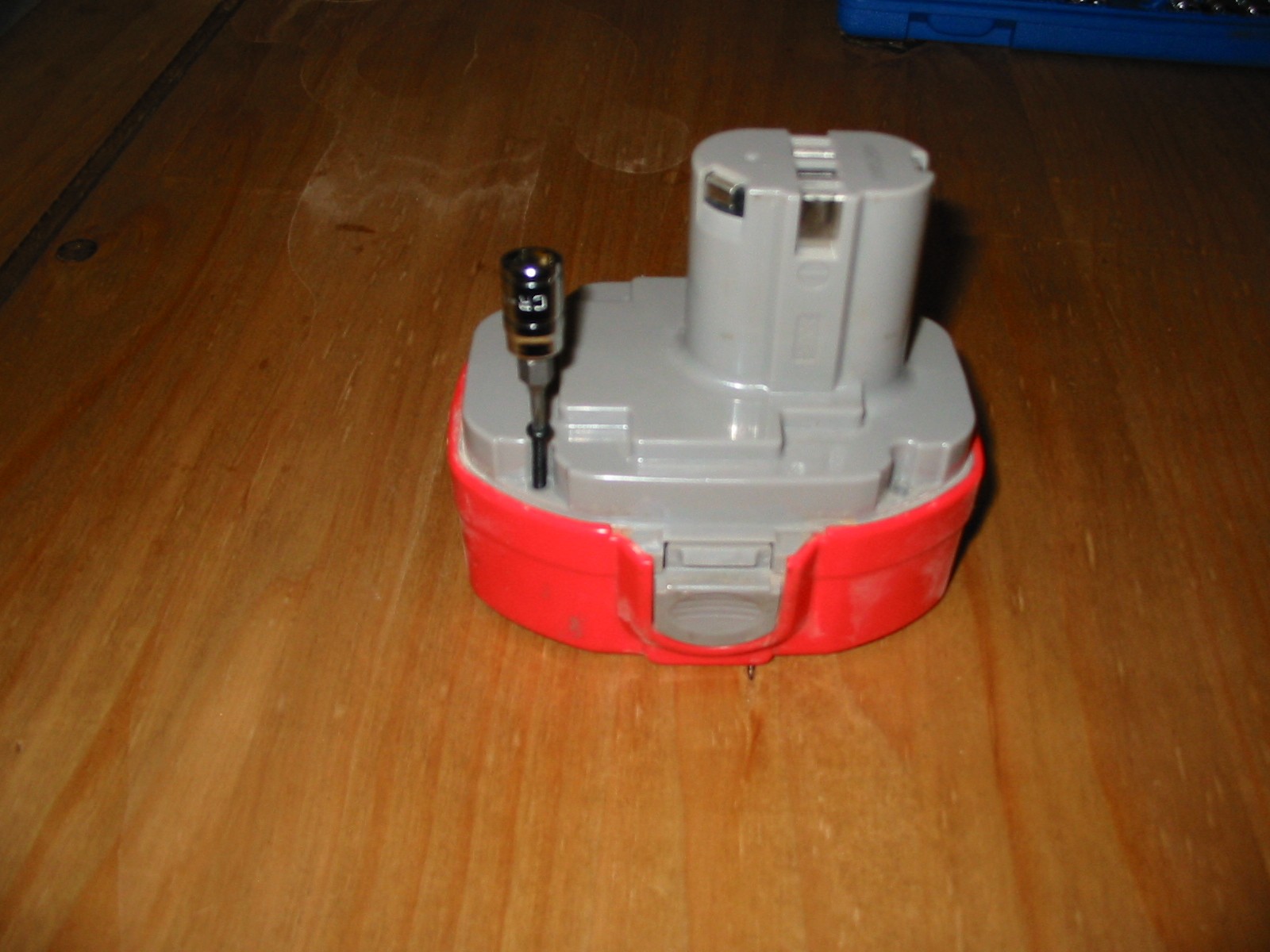
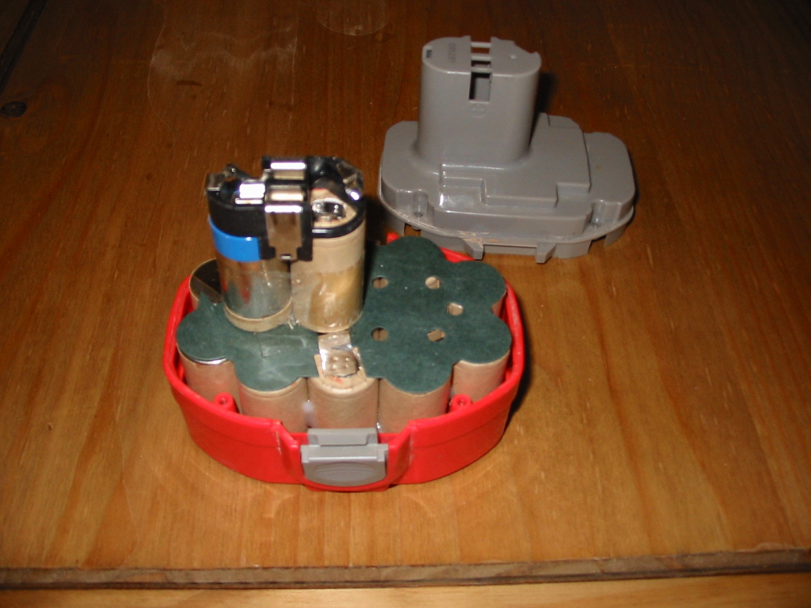
2. Dismantle Battery holder by removing the 4 off Torx Screws T10. Press
the two grey thumb retaining clips and gently pull the grey top top unit
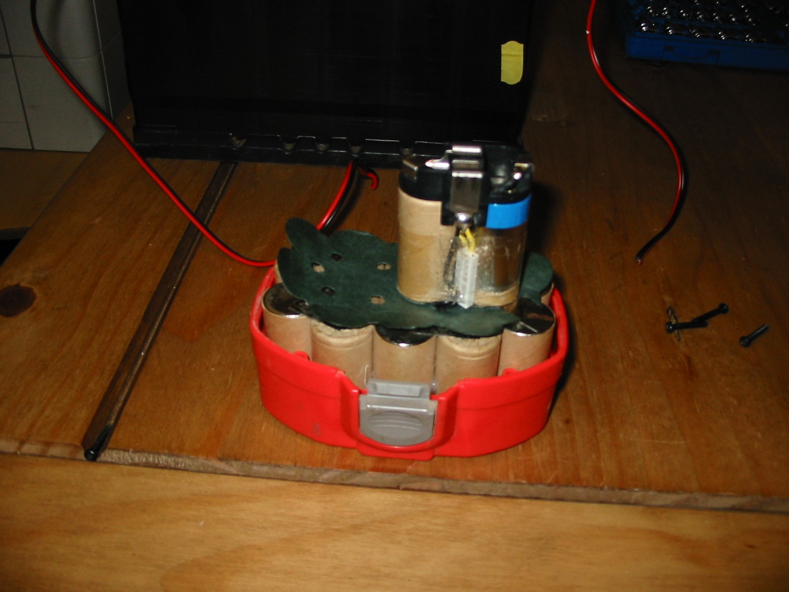
apart from the red base using a rocking action. This will display the Nicad
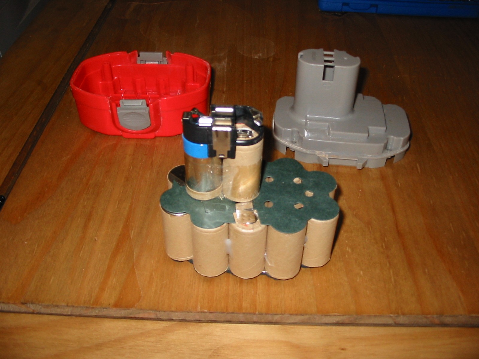
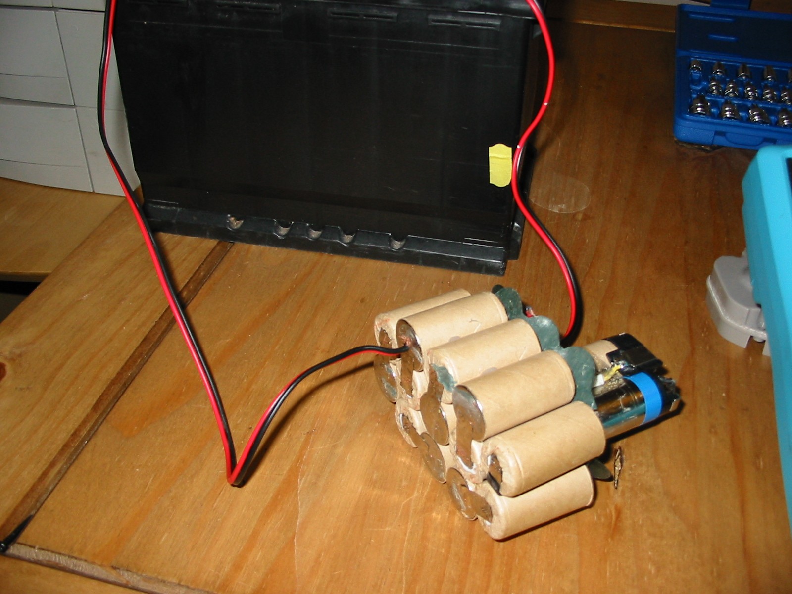
Module made up of 15 individual 1.2v cells
3. holding the outer edge of the main battery module ( Not the top 2 cells )
gently pull the battery module out of the red lower case.
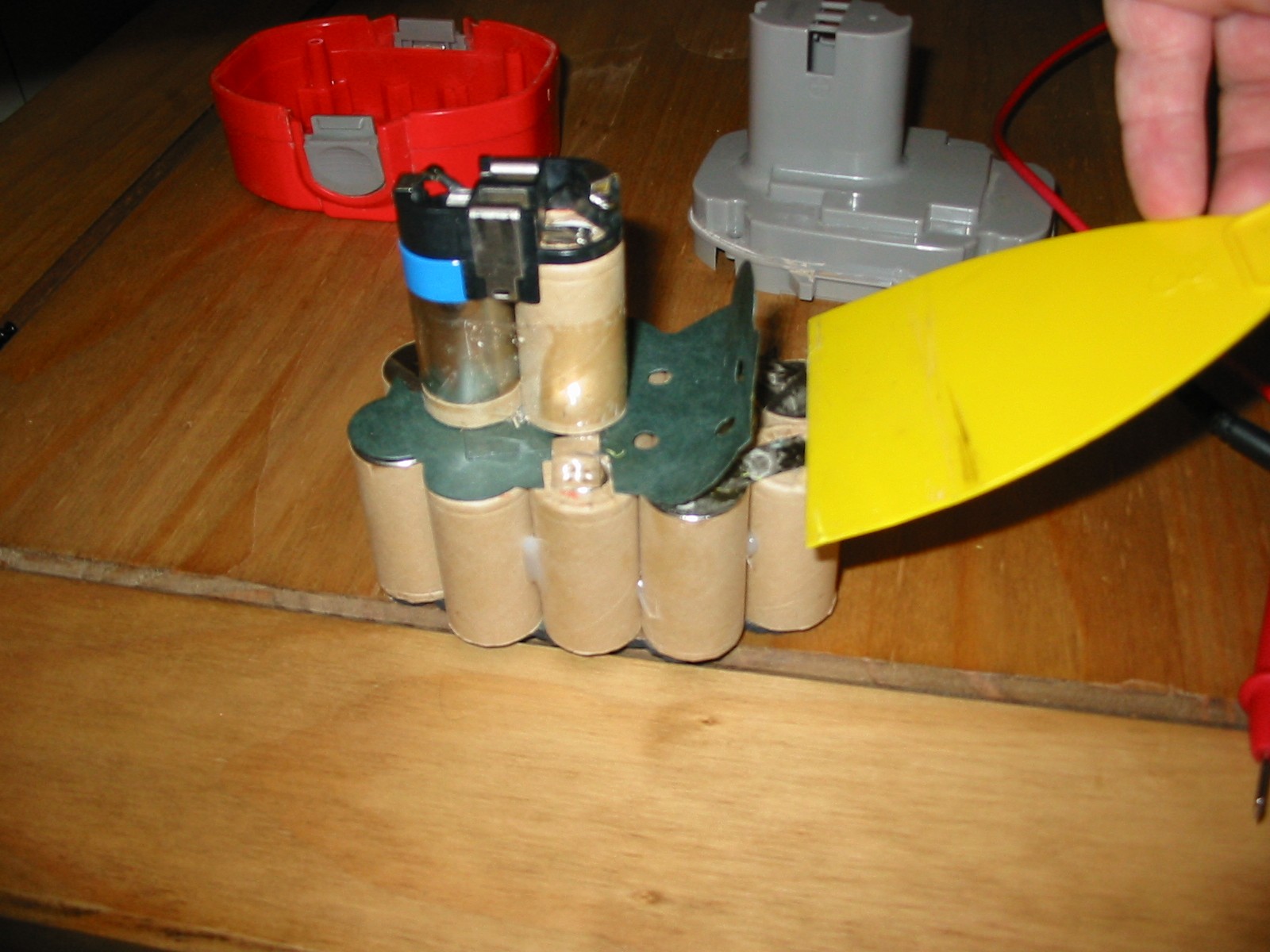
4. Using a plastic scraper lift the top green insulator card from the top face
exposing the cell electrical connections. ( Do not pull off ). Next repeat the
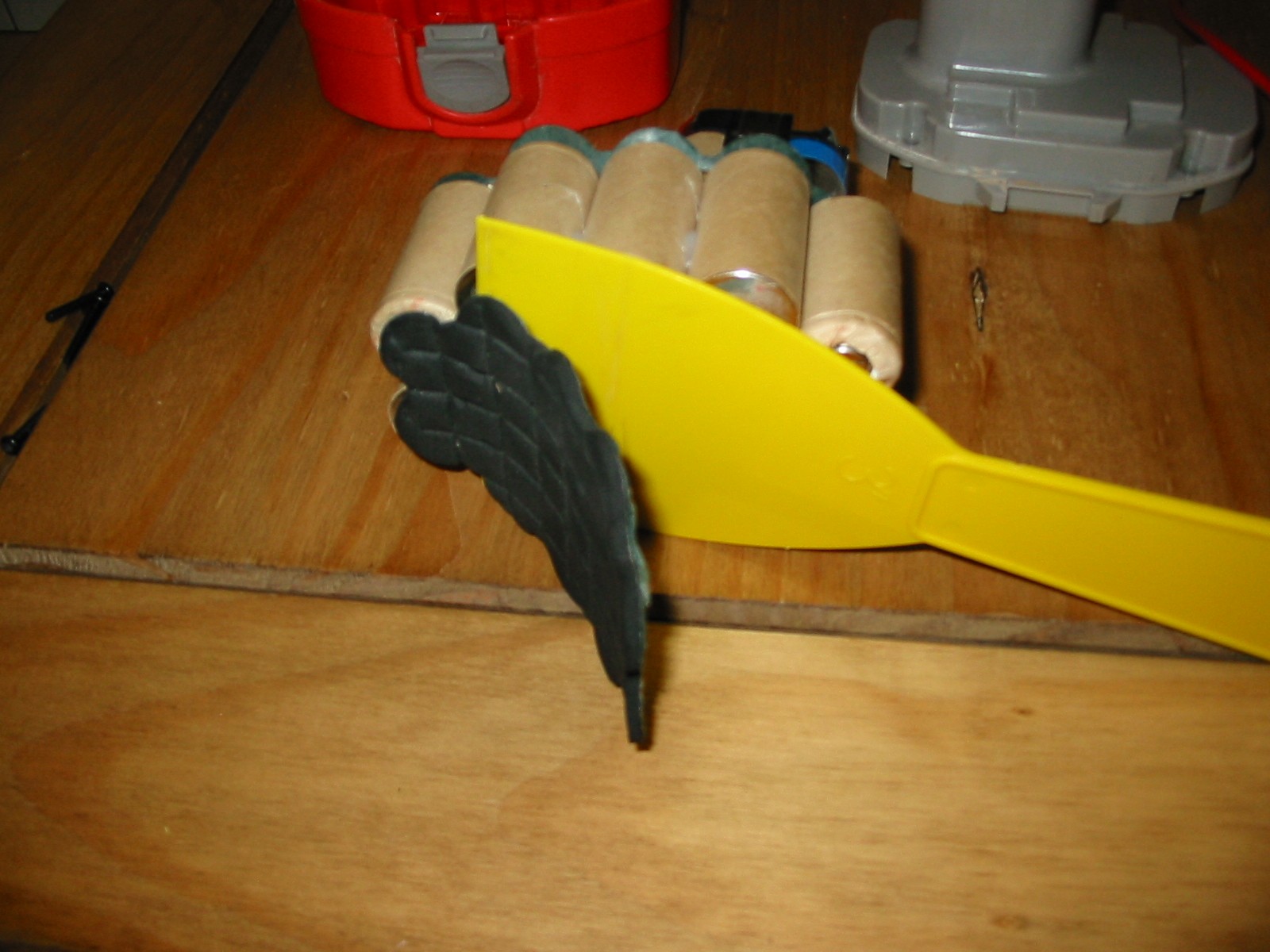
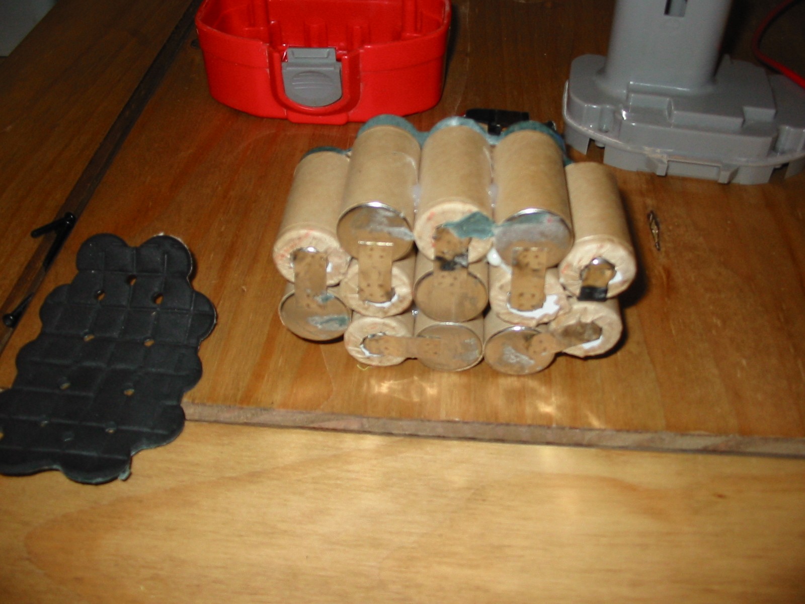
same process on the bottom of the module but removing the black foam
insulator, again exposing the bottom cell electrical connections.
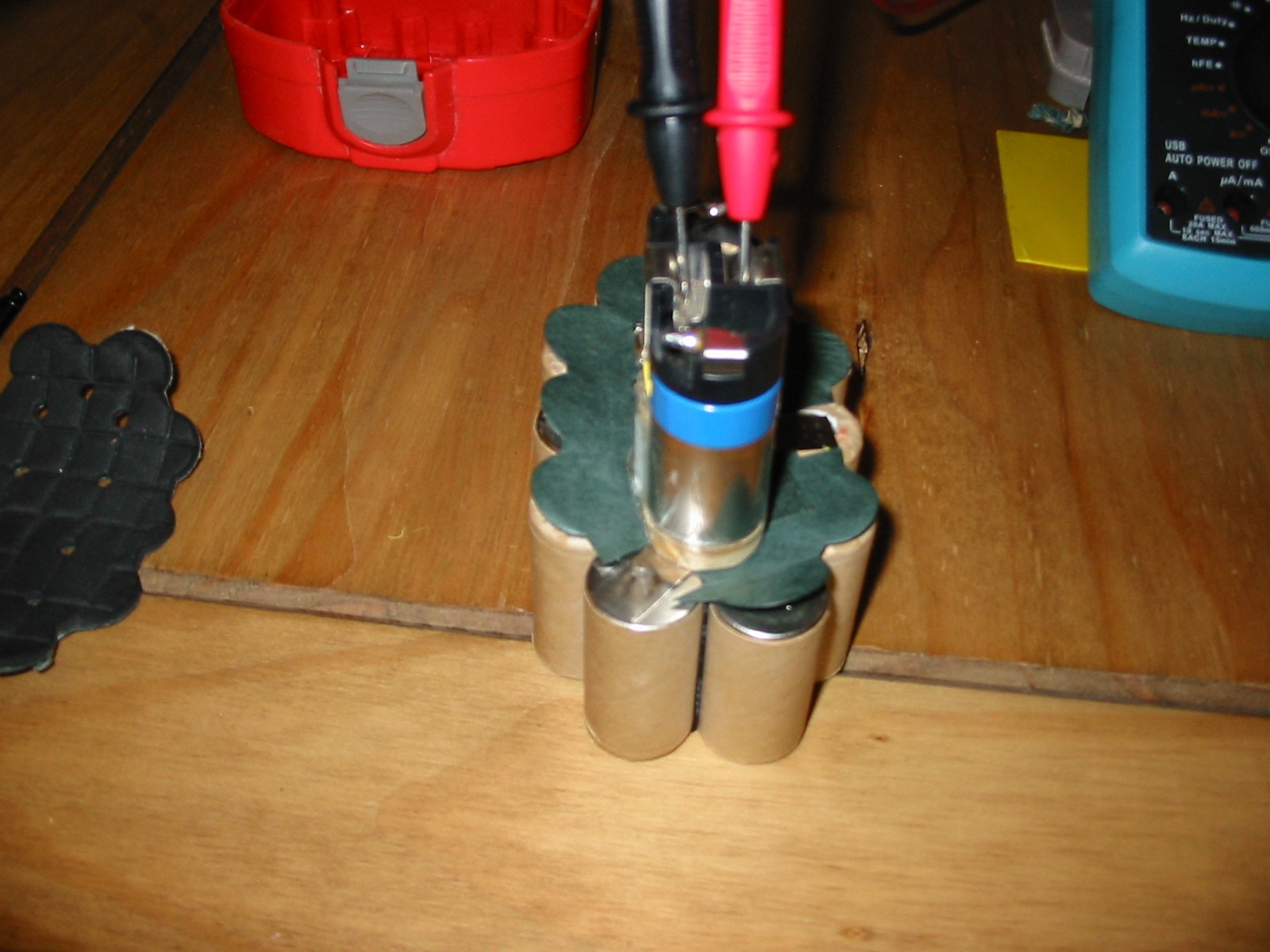
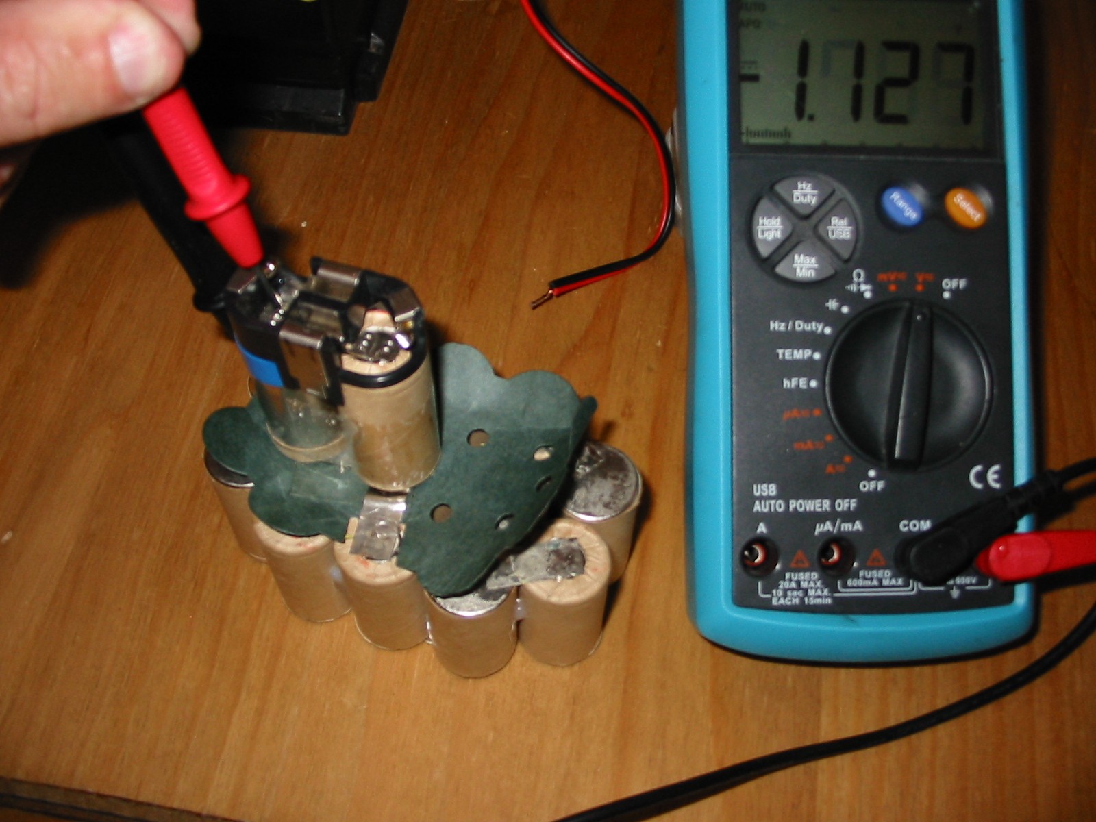
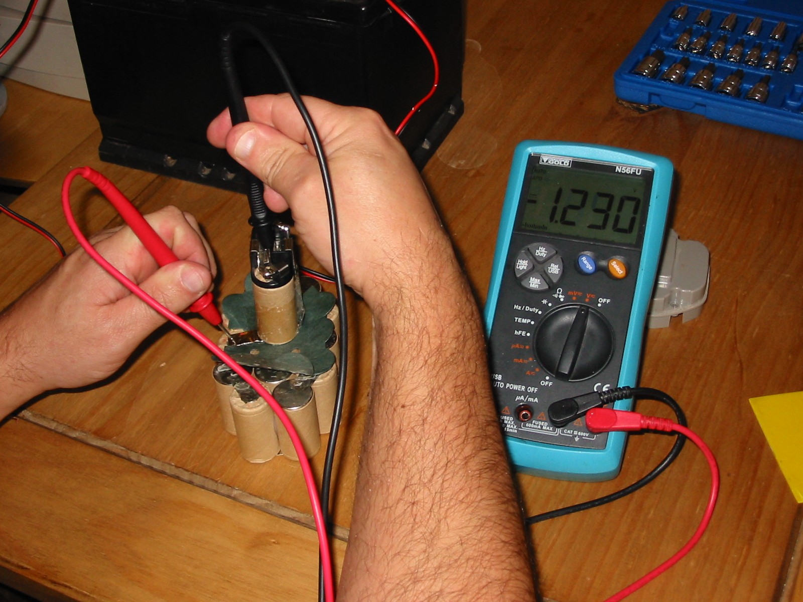
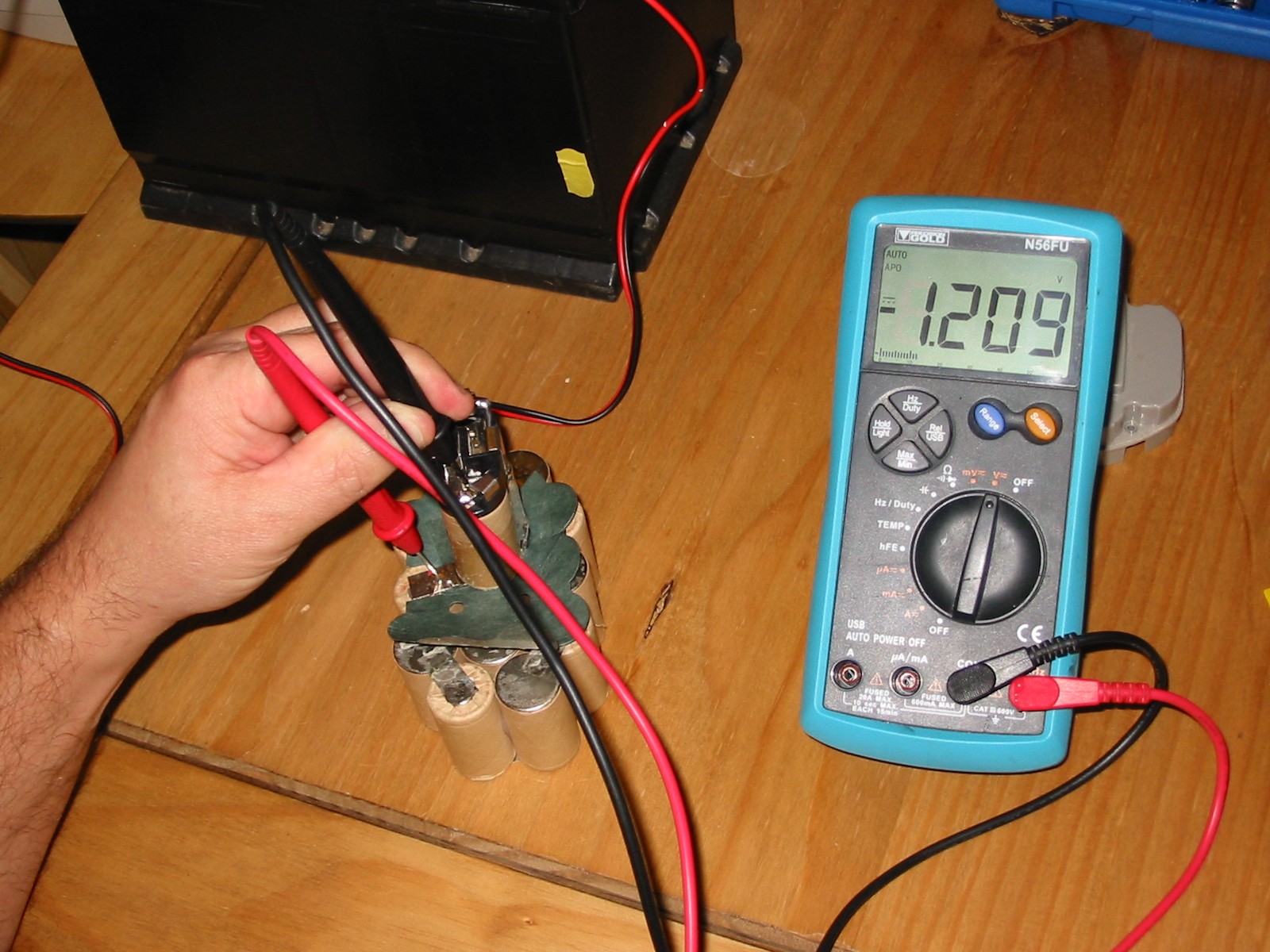
5. At this stage you can check the voltage of each individual Cell and make
note of any cells that are displaying significantly lower voltages.( Mark call
if required with pencil for Reference only )
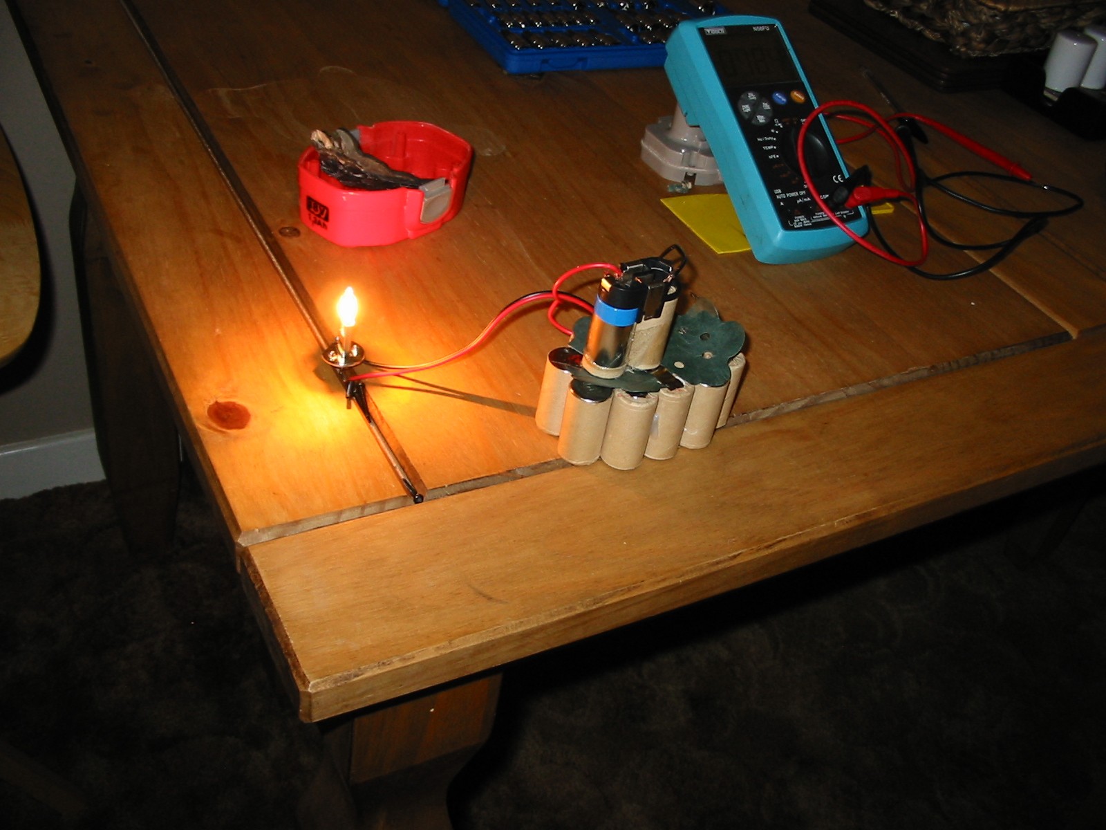
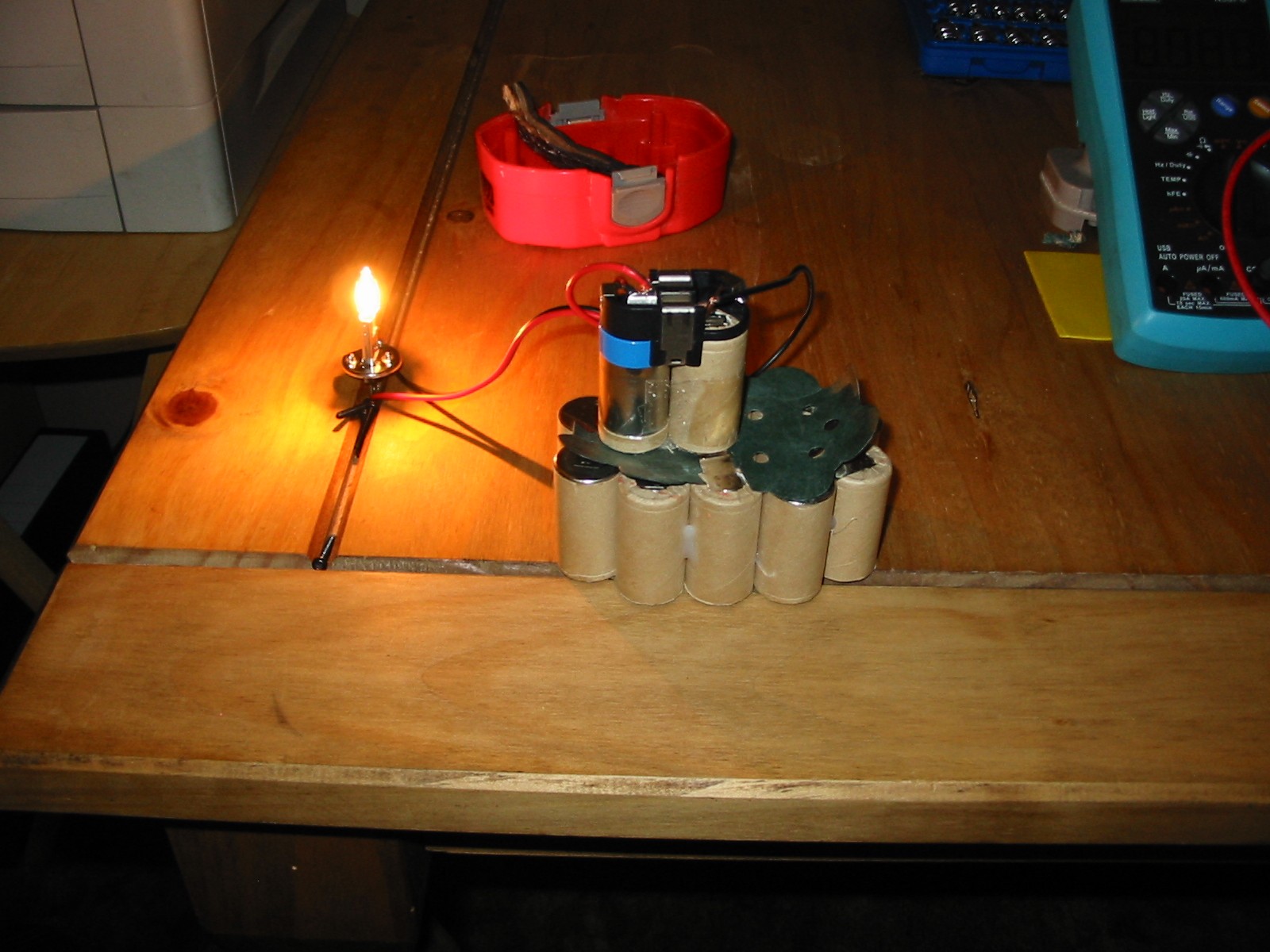
6. The next step was to discharge the complete battery module. I used a car
head lamp bulb placed across the battery pack. I left this on for about 15
Mins to ensure the unit is completely discharged.
7. If the battery contained any significant charge and the battery module is
warm or hot after the discharge process, Place the battery module in the
fridge/freezer for 10mins or so to cool the cells back down.
8. Note the cells are wired in series to generate the 18v so the + and -
orientation is opposite. This is indicated by the small connection being the
positive and the main bottom of the cell being flat Negative. Please check
polarity with the multimeter.
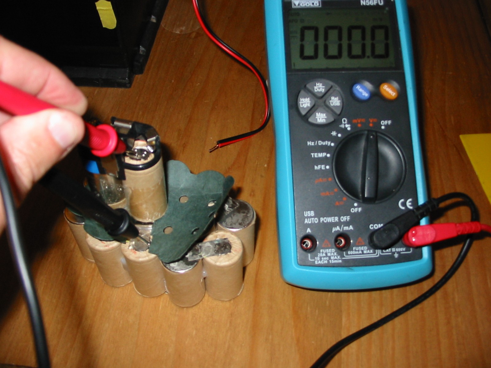
9. When you check the individual cells again you will probably see most of
the cells reporting 1.1v or so but 1 or more of the cells will return 100mv or
even 0V,
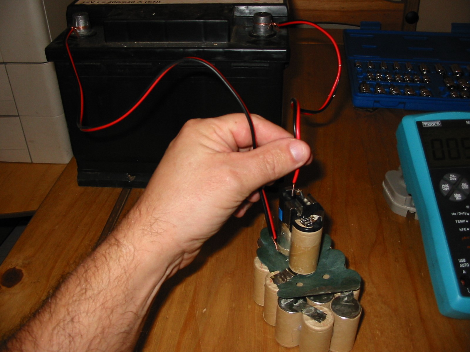
10. Next take the car battery, or similar voltage supply that will withstand
a surge voltage situation, I used a Spare car battery. Note these can pull
well in excess of 100A and will melt car wires very quickly and will catch
fire if left in short circuit contact for more than 1 second or so.
11. Warning ! ( Any actions you take at totally at your own risk, ) This
process has an element of risk, Please use safety gloves and glasses for this
process. What could go wrong? Any of the individual battery Cells could
Explode during the power surge process. The wires from the power source
could melt and burn your fingers if to thin. Power source could be damaged
or explode under surge conditions If you decide to follow any of this
process please be safe and use safety gear to protect yourself.
12. The power shunt process, take two wires from the car battery making
sure the +/- is clearly identified on the wires. This process is the like
striking a match NOT a direct connection of wires to cell.
13. At this point it is very important to ensure you make contact of the
positive wire to the positive battery cell and Negative wire to the negative
Cell. Push one wire onto the cell and strike the other like striking a match
to light it, the end of the wire should spark against the cell. this strike may
be done 2 to 3 times per cell on all 15 cells. You can then repeat this
process for all cells. WARNING! Do not hold the wires directly on the cell
it will likely explode or melt wires. ( It must be a striking action )
14. Check the voltage of all individual cells they should return a minimum
of 1.2v stable on all cells. If any of the cells still look incorrect try another
power surge process on the cell in question. Of you are still unable to
obtain a 1.2V reading on the cell this cell may be scrap and require
replacement.
15. Replace the black insulation foam on the bottom of the module and
push the insulation covering on the top of the module back down. Then
reassemble the battery pack in reverse process of above.
Place the battery pack onto the standard battery charger for the full
charge cycle and test for improvement.
